l Network resistors
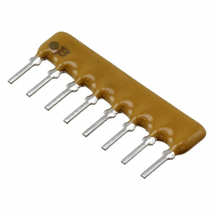
In the circuit design, the network resistor is also used. The network resistor has the advantage of being neat and less space-consuming than the color ring resistor. The inside of the circuit is actually arranged neatly by a plurality of resistors. There are two types of network resistors.
Note: Network resistors are the resistors commonly used in circuits.
1.Dual in-line network resistor
The dual in-line network resistor is similar to the IC. The first pin is represented by a dot or a small groove. When you hold the component, the component body faces itself, the slot or small dot is up, and the first one on the left. The pin is the first pin. The holes for the first pin are usually marked on the board with square or pointed pads. When plugging in the network resistor, the first pin must be inserted into the board with the hole labeled the first pin.
2.Single in-line network resistor
A single in-line network resistor is a plastic box with a row of pins. The symbol in the circuit is "RN
RP", "1B"
The first pin is indicated by a small dot on the component body or the number "1" or a thick solid line. The first pin on the board is usually represented by a square pad or a dot. The first pin is usually inserted into this square pad or next to a small dot.
Network resistor :4608X-101-181LF
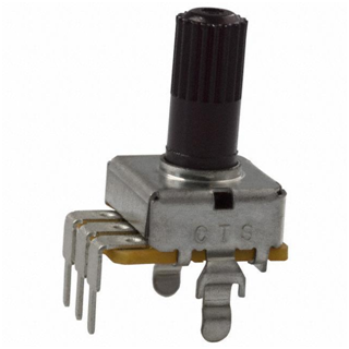
l Potentiometer : adjustable resistor
The potentiometer is an adjustable resistor. Its symbol in circuit is Rp. The resistance can be changed by adjusting the knob or screw on the component body. The potentiometer is directional. A potentiometer has three pins and there is only one way to insert the potentiometer into the board. The shape of the potentiometer is square, circular and rectangular.
Generally speaking, it is easy to judge the quality of the resistor by using a multimeter:
In general, it is easy to judge the quality of a resistor using a multimeter:
Adjust the resistance block of the multimeter to the appropriate resistance value and placing the two test leads on both ends of the resistor.
It should be noted that the hand cannot touch the metal part of the test lead when testing the resistance. In actual electrical maintenance, resistance damage rarely occurs. The important thing to note is whether the resistor is soldered (false solder) or stripped. The shape of the resistor is shown in the figure.


No comments:
Post a Comment