1. Point Bitmap program installation.
Micro-star motherboard point bitmap view software is a ICGE program. IGE is a direct-running program that is used in the same directory as the IGE.DLL file, as shown in figure 1.

Fig.1 IGE programs and fil
Double-click directly to run the program, the program after the interface is shown in figure 2.
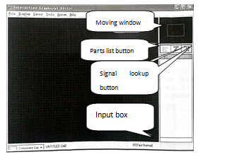
Fig.2 IGE Program button description
2. Tool description.
On the right side of the window is a selection and lookup toolbar with the corresponding tool buttons, as shown in figure 2.
(1) Window: click in different locations in the window and you can display components from different locations on the motherboard in the window.
(2) List of parts button: click to find the appropriate components.
(3) Signal lookup button: click to find the corresponding signal.
(4) Input box: input information when looking up components or signals.
3.Sept1, click the File main menu, as shown in figure 3.
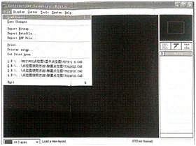
Fig.3 File Main menu
Step 2, click Doad Layout to find the point bitmap sequence source location, as shown in figure 4.
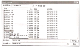
Fig.4 Select Program source
Step 3, select the program source and click the Open button to load the program source, as shown in figure 5.
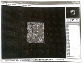
Fig.5 Program source loading effect diagram
Step 4, click the parts list button and enter the find component location number R110 in the find box, as shown in figure 6.
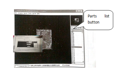
Fig.6 Component lookup input effect
Step 5, double-click the R110 component tag, and then the mouse will direct to the R110 position, and the resistor R110 will display white, as shown in figure 7.
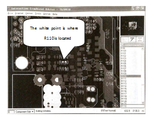
Fig.7 Component display effect diagram
4.Signal lookup method.
Step 1, click the signal Lookup button, as shown in figure 8.
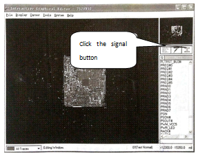
Fig.8 Signal lookup button
Step 2, enter the name of the signal you want to find in the input box, and this example enters the RSMRST signal, as shown in figure 9.
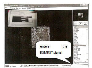
Fig.9 Signal input box
Step 3, double-click the corresponding name of the signal, in the window will be a flash white line, is the signal line, as shown in figure 10.
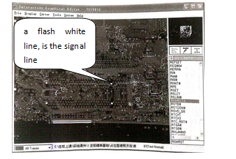
Fig.10 Signal alignment effect diagram
5.Connection point finding method
If you want to find the pin connection position, right-click on the component location, and then the connected line becomes white and flashes, as shown in figure 11, and the right-click again disappears.
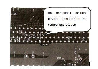
Fig.11 Line route

No comments:
Post a Comment