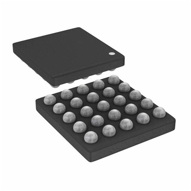
The biggest challenge in integrating an FPGA into an embedded system is how to configure the logic of the FPGA and connect the sensor inputs and control outputs to it. Many embedded system designers are very skilled at programming on microprocessors running under real-time operating systems, but they don't like to define hardware at the chip level, which requires knowledge of design tools and languages such as VHDL. Of course, taking the liberty into the chip-level world also means designing and building boards around the chip. Although this is outdated for some embedded system designers, there are still many designers who prefer to use off-the-shelf hardware whenever possible. Especially when the hardware has to accurately measure and digitize the sensor data.
There are many FPGA configuration tools available, some require VHDL or other language coding to complete the hardware definition, some provide a graphical configuration environment, and others allow you to write software using familiar tools and then download the code to the FPGA. There are a few issues to consider when choosing which method to use, one of which is your background. Are you an experienced hardware developer and have an in-depth understanding of the basic operation of the FPGA? If so, you can use low-level tools to get the most out of your experience and go deep into the field. Maybe you are not a hardware engineer, but you are a good programmer and can easily master a new programming language, then you may need to choose a tool that allows you to fully utilize the data structure and program details to program. Another possibility is that you are neither a hardware expert nor a software expert, but because you are very familiar with the application of the theory or system in the whole system, if you are in this situation, you should choose one that will allow you to Tools for designing your own language without having to learn complex FPGA or hardware description languages.
Another important consideration is what is required by the system you are planning to design. If you are designing multiple different types of systems, a common hardware design tool might be the best fit. There are many people who spend a lot of time becoming experts in using these tools, and you can join them. If you want to narrow down the scope, there are tools to deal with those "regular" issues, and let you focus on where you can add value. For example, there are a number of tools that can help you quickly develop a signal processing system and configure it into an FPGA. There are also some optimized tools designed to add measurement and control.
Also need to consider the problem of how the system configuration wants to be set. What size do you have? Is it connected to a PC? Some FPGA development tools require you to develop all the hardware around the FPGA, while others require a special board with an FPGA built in. For the latter, many of the work on the board with other resources such as I/O and bus connections is done, which can greatly speed up the development process, because you do not need to pay attention to things such as noise immunity, settling time and crosstalk. For such systems, you should make sure that the connection to I/O has only a few simple features. If your system requires a lot of connectivity to a PC running Windows or RTOS, you should choose a design tool that is cross-platform. If the API used to develop the PC-side interface is very limited, the design efficiency will be affected to some extent.


No comments:
Post a Comment