Wednesday, July 31, 2019

What are the methods for shielding PCB design interference?

The transmission rate of high-speed PCB design and wiring systems is steadily increasing, and it also brings some kind of anti-interference vulnerability. The higher the frequency of transmitting information, the increased sensitivity of signals, and their energy is getting weaker. The wiring system at this time is more susceptible to interference. Interference is ubiquitous, andcables and equipment can interfere with other components or be severely interfered with by other sources of interference, such as computer screens, mobile phones, electric motors, radio equipment, data transmission, and power cables. In addition, potential eavesdroppers, cybercrime and hackers are increasing because they can cause huge damage and loss in the interception of UTP cable information.

Especially when using high-speed data networks, the time required to intercept large amounts of information is significantly lower than the time required to intercept low-speed data transmissions. The twisted pair in the data twisted pair can resist its external interference and crosstalk between the pairs at its low frequency, but at high frequencies (especially when the frequency exceeds 250MHz), Wire twisting has not been able to achieve the purpose of anti-interference, only shielding can resist external interference.

The cable shield acts like a Faraday shield, and the interfering signal enters the shield but does not enter the conductor. Therefore, data transmission can run without problems. Since shielded cables have lower radiated emissions than unshielded cables, network transmissions are prevented from being intercepted. Shielded networks (shielded cables and components) can significantly reduce the level of electromagnetic radiation that can be intercepted into the surrounding environment.
The shielding field of different interference fields is mainly composed of electromagnetic interference and radio frequency interference. Electromagnetic interference (EMI) is mainly low frequency interference, and motors, fluorescent lamps, and power lines are common sources of electromagnetic interference. Radio Frequency Interference (RFI) refers to radio frequency interference, mainly high frequency interference. Radio, television, radar and other wireless communications are common sources of RF interference. For resisting electromagnetic interference, the choice of braided shield is most effective because it has a lower critical resistance; for radio frequency interference, the foil layer shielding is most effective, because the braided shield depends on the wavelength change, and the gap created by it makes the high frequency signal free. In and out of the conductor; for high-low frequency mixed interference field, a combination of foil layer and woven mesh with broadband coverage is used. In general, the higher the mesh shielding coverage, the better the shielding effect.
image.png 

Tuesday, July 30, 2019

The application of capacitors on motherboard

A capacitor is a component that holds a charge and is represented by the letter C. Capacitors have the functions of charging and discharging. In mainboard circuits, capacitors are mainly used for power supply filtering, signal coupling, resonance and so on. In circuit diagrams, the capacitance is usually represented by the symbols shown in figure 1. The mainboard of the desktop uses a straight-in capacitor (see figure 2) and a chip-mounted capacitor. The direct-inserted capacitor is mostly used in the filter of power supply circuit, and the filter capacitor has positive and negative electrodes. If the positive and negative electrodes are installed, the capacitance will be damaged and the capacitor will explode seriously. The capacitor case has a white or marked one foot as a capacitor negative pole, no mark one foot as a positive pole. The common polarity of the direct capacitor is electrolytic capacitance, solid-state capacitance.
       image.png
          aNonpolar capacitance     bPolar capacitance
                        Fig.1 Capacitance symbo
                        image.png
                      Fig.2 Direct-inserted capacitance

Note: when installing motherboard capacitors, the positives and negatives of the capacitors on the motherboard should be carefully measured to prevent reverse mounting. Ordinary motherboard PCB has a white shadow is negative, Asustek and Hua Qing motherboard capacitive position of the opposite, white shadow is positive at one end, should be very careful installation.

According to the appearance, the patch capacitor (see figure 3) can be divided into two types: single capacitance and row capacity. The patch capacitor is used not only for filtering, but also for coupling, resonance, voltage-up and so on.
                     image.png
                        Fig.3 MLCC

This article is from Allicdata Electronics Limited.
Allicdata Electronic specialize in the production of safety capacitors, varistors, ceramic capacitors, film capacitors.
If you are sourcing the products, please contact us, we will try our best to solve it for you. For more product information, please go to the website to get it.

Monday, July 29, 2019

Methods for repairing LCD color TV with oscilloscope

l  Determine the fault range based on the fault characteristics of the waveform
In a faulty LCD color TV, the waveform changes are very different, but there are still some rules to follow, and the analysis mainly includes the following situations:

(1) Waveform amplitude and frequency deviation are too large
The waveform amplitude deviation is too large, reflecting that the circuit is not working properly. For example, the coupling capacitor variation or the resistance of the feed branch resistor increases, which generally attenuates the amplitude of the waveform. The change in the operating point of the amplifier also causes the amplitude of the waveform to change.
The waveform frequency deviation is too large, in addition to the waveform frequency offset, it should also include pulse width aberration. Pay attention to observation and analysis during maintenance.

(2) no waveform
This situation reflects that the signal is not sent to the detection point, it may be that the circuit has an open circuit, the signal is interrupted, and there may be a short circuit between the point and the ground.

(3) There is a clutter in the waveform
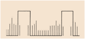
A clear waveform is not visible on the oscilloscope, but many lines are superimposed or displayed in a messy manner. One of the waveform lines is brighter and the others are darker, which is usually called the waveform "not clean", as shown in the following figure. The cause of this failure is the failure of the filter capacitor, leakage of some components or boards, and so on. Of course, if there is a power transformer near the oscilloscope working or the oscilloscope is poorly grounded, it will also cause such interference.
 image.png
(4) Distortion of waveform shape
Causes of waveform distortion, common capacitors, resistance variable values, etc., and some are caused by the malfunction of the amplifier.
(5) An oscillating wave is superimposed on the waveform, indicating that there is parasitic damped oscillation in the circuit, which is more common in switching power supplies or high voltage circuit. The frequency of the parasitic oscillation is high, and it is easy to be radiated by the circuit, and then the circuit forms interference.
(6) Waveform reversal
The waveform reversal means that the test waveform is opposite in phase to the normal waveform, the forward pulse becomes a reverse pulse, or the reverse pulse becomes a positive pulse, and the oscillation wave is superimposed on the amplifier waveform to work abnormally or the gate circuit does not work. Caused normally.


l  When using an oscilloscope to repair LCD TVs, there are several common methods.
    1. Joint probe measurement
For dual-track oscilloscopes, there are usually two 10:1 attenuation probes. When measuring high-amplitude voltage waveforms such as reverse pulses, if there is no 100:1 probe, you can also connect these two 10:1 probes in series. And make up a 100:1 probe. When in use, both probe attenuation switches are set to ×10 position, which are connected end to end, which is very convenient to use.


    2. Signal tracing
The signal tracing method is to measure the voltage waveform of certain key points or extended measurement points along the direction of the signal according to the fault phenomenon during the process of repairing the liquid crystal color TV. The operator only needs to master the circuit structure of the color TV, master the characteristics of the key signals and the normal waveforms. By testing the test points, the fault location can be quickly found. This is the most common method used in maintenance.

3. Monitoring measurement
For faults that occur irregularly, or that may occur during a long test, monitor measurement is used to attach the oscilloscope probe to the suspected measurement point for a longer period of time. If the lead or solder joint of the measured point is too small, it is not convenient to suspend the probe. You can add a thin hard wire with a solder length of no more than 1cm on the solder joint, but be careful not to short-circuit the other solder joints nearby. Lightly hang the oscilloscope probe on the wire, do not pull the copper foil on the board

How to order LC4128ZE-7TN100C IC CPLD 128MC 7.5NS 100TQFP Lattice ?

Q1: How to order LC4128ZE-7TN100C IC CPLD 128MC 7.5NS 100TQFP Lattice ?
A: You can purchase orders directly online at our website:
Open our home page >Quick search   LC4128ZE-7TN100C > on Produce page click Buy > Finish all the step shows
Or send your PO to our email sales@allicata.com
Or chat with our online service.
The ordering steps are as follows:
Check price → purchase order → payment →shipment delivery out → receiving materials
For a large number, you can get a better price.

Q2: How long of the delivery time of LC4128ZE-7TN100C IC CPLD 128MC 7.5NS 100TQFP Lattice ?
A: ALLICDATA has more than 1M + stock, so that we can  delivere it worldwide by Fedex, DHL, UPS within 2-3 days.
Q3: What's the MOQ of LC4128ZE-7TN100C?
A: ALLICDATA MOQ  order from 1 unit.

Q4: Where can find the pictures of LC4128ZE-7TN100C IC CPLD 128MC 7.5NS 100TQFP Lattice ?
A: We have provided original images of STOCK Parts. You can search for photos on our website via the search box.


Q5: How much of LC4128ZE-7TN100C IC CPLD 128MC 7.5NS 100TQFP Lattice ?
A: ALLICDATA Electronics offers more than 1,000,000  items in stock with immediate shipment,which has a competitive price.LC4128ZE-7TN100C IC CPLD 128MC 7.5NS 100TQFP Lattice  Real-time inventory quantity and price,please search online catalog on our website:Allicdata Electronics.


Q6:How to pay for LC4128ZE-7TN100C IC CPLD 128MC 7.5NS 100TQFP Lattice ?
A: ALLICDATA accepts payment by bank wire transfer (bank TT), Paypal, credit card, Western Union, letter of credit, etc. You can choose whatever way you like. We make sure that these methods are safe.

Q7: How do I receive LC4128ZE-7TN100C IC CPLD 128MC 7.5NS 100TQFP Lattice ?
A: ALLICDATA can provide Fedex, UPS, DHL and TNT, door-to-door services, for some samples we can deliver via EMS.

Q8: How to get better price of LC4128ZE-7TN100C IC CPLD 128MC 7.5NS 100TQFP Lattice ?
A:For a large number, you can email us for a better price.

Q9: How to find data sheet (PDF) of LC4128ZE-7TN100C IC CPLD 128MC 7.5NS 100TQFP Lattice ?
A: We have huge datasheet base.Almost all produce data sheet can be found quickly on our website. Or click this link :
If you need any help, please contact us.

Q10: What's quality guarantee of LC4128ZE-7TN100C?
A: All ALLICDATA products are licensed by the manufacturer and are 100% NEW & ORIGINAL. If there are any problems, we accept the return within 60 days.

Q11: Where can I find the shipping of LC4128ZE-7TN100C IC CPLD 128MC 7.5NS 100TQFP Lattice ?
A: You can track Fedex, DHL, UPS, TNT office websites in all our transportation. We will send a tracking link after shipping.

If this model does not meet your requirements, you can go to our website Allicdata to search for products that match. There are many kinds of products that can be selected.

LC4128ZE-7TN100C Allicdata Electronics

Thursday, July 25, 2019

Research finds that LED can replace laser as a method of transmitting near-infrared light

According to reports, Hanli Liu, a professor of bioengineering at the University of Texas at Arlington, is working to improve the memory and cognitive functions of astronauts in space missions by illuminating the astronauts' brains.

It is reported that she and Jacek Dmochowski, assistant professor of bioengineering at the City University of New York, received a $800,000 grant from NASA to study light-based technologies to increase the available energy of astronauts' brain cells and improve the performance of astronauts.

Her job is to study how to use lasers to provide near-infrared light to the human brain to detect symptoms of traumatic brain injury and post-traumatic stress disorder. Recently her work has been extended to study the neurophysiology of non-invasive transmission of near-infrared lasers. Principles to improve human cognition. The study taught people how light stimulates mitochondria and produces more oxygen in the brain to increase brain metabolism and reduce memory loss.

With funding for this new project, she will investigate whether LEDs can replace lasers as a means of transmitting near-infrared light. Specifically, she wanted to find the wavelength range and duration needed to produce the desired effect.

In general, lasers are heavy and bulky, taking up too much space in the narrow space of a spacecraft or space station. LEDs are lighter and smaller and can be more easily mounted on headbands or similar devices. In addition, LEDs are safer to the human eye than light from a laser.

LED light in the red and near-infrared range has been widely used to relieve pain and treat acne, but few researchers have rigorously studied the feasibility and limitations of promoting and stimulating brain metabolism.

The researchers have evidence that memory can be improved after 8 to 10 minutes of exposure to specific areas of the human brain,” she said. “We are demonstrating that if we can increase the power of LEDs at a safe level, we can Make the LED light reach the cortex like a laser, but it's safer, smaller, and easier to use."

What has the development of smart cities brought to the sensor industry?

Human beings entered the 21st century and entered the information age in an all-round way. In a certain sense, they entered the era of sensors. In the modern control system, the sensor is in the position of the interface connecting the object to be tested and the test system, and can directly or indirectly contact the object to be measured, which is the eye of the Internet of Everything, directly affecting and determining the performance of the system.

At present, the Internet of Things, big data, cloud computing technology, and even the realization of various technologies in smart cities, which are highly regarded by the international community, are particularly dependent on sensor technology.
Smart cities drive sensors to form bigger markets
Smart cities are connected in the city, and sensors need to be installed on every object that needs to be identified. Therefore, the upgrading of sensors has become the key to the rapid development of smart cities. In Santander, Spain, buildings and streetlights are filled with 25,000 sensors for measuring light, noise, carbon emissions, temperature, h-umidity and pressure, while roadsides have geomagnetic sensors that monitor roads and parking conditions.
With the vigorous development of smart city construction, the sensor industry will also form a larger market. The Internet of Things and smart city will be the main application market for sensors in the future.

CMOS image sensor suddenly rises
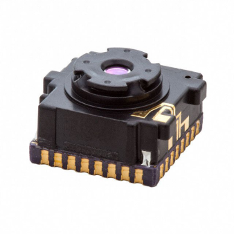
 Image Sensors :500-0643-00

image.png
In recent years, intelligent video surveillance system has achieved rapid development as one of the main data sources of smart cities. In the field of video surveillance cameras, image sensors, as one of the key factors determining image resolution, will also usher in further development.
In the field of IP surveillance, CMOS has better image performance, lower cost, higher integration, lower power consumption and faster speed than CCD, so it is increasingly used in network cameras. With the development of large-resolution, high-frame rate, low-cost image sensors and the development of technology, CMOS image sensors have become the mainstream of today's image sensor market due to their high integration, excellent performance, and ease of use. .
In addition, the optical sensor market is becoming more and more powerful, and CMOS image sensors will be used more and more in machine vision equipment. Technologies and products such as drones, robots, virtual reality (VR) and augmented reality (AR) will also make the CMOS image sensor market a new life.

Three types of sensors welcome a broad space for development
The development of smart cities, for the sensors that are the core of the IoT perception layer, will be a good time for development in the coming decades, and the development space is broad.
It is foreseeable that special-purpose sensors for special industries and sensors with high precision will have a lot of room for development. In addition, as access control systems in commercial and residential applications are popularizing biometrics, this type of sensor will usher in the spring of development.
Conclusion: With the advent of the new technological revolution, the world has entered the era of information intelligence. In the process of using information, the first thing to be solved is to obtain accurate and reliable information, and the sensor 

What are the main reasons for the failure of the connector connection?

The inner conductor of the connector is smaller in size relative to the outer conductor, and the inner conductor having a lower strength is more likely to cause poor contact and cause the connector to fail.

Most of the inner conductors of the connector are elastically connected, for example, a spring claw type elastic connection, a jack slot type elastic connection, a bellows type elastic connection, and the like. The jack slot type elastic connection structure is simple, the processing cost is low, the assembly is convenient, and the application range is the most extensive.
image.png

1, the inner conductor is not fixed firmly
For assembly purposes, in many RF coaxial connectors (eg, N-type, 3.5 mm), the inner conductor is divided into two sections at the media support and then threaded. However, due to the small diameter of the inner conductor, if the glue is not fixed at the screw connection during assembly, the strength of the inner conductor connection is very poor, especially for some small RF coaxial connectors. Therefore, when the connector is connected and disconnected multiple times, under the long-term action of the torque and the pulling force, the inner conductor thread may loosen and fall off, resulting in the connection failure.
One of the commonly used structures of RF coaxial connectors is that the inner conductor, the dielectric support, and the outer conductor are held together by means of an adhesive. If the structure is insufficient in the assembly or the connection strength of the glue is insufficient, the glue may be broken due to the force during use, which may cause the inner conductor to rotate or axially move, and between the inner conductors. Failure to form a good electrical contact and failure of the connection.
Improved method: When the coaxial connector is assembled, apply a proper amount of conductive glue or thread locker at the threaded joint to increase the reliability of the threaded connection. It is necessary to select an adhesive with high bonding strength, and it is necessary to ensure that the glue fills the entire glue coating hole when the glue is applied; the inner conductor is glued to knurl, increase the contact area between the inner conductor and the adhesive, and prevent the inner conductor from rotating; The radial dimension and tolerance of the conductor, the outer conductor and the medium support make the inner conductor and the medium support, the medium support and the outer conductor have an interference fit, and the three components can be assembled more firmly.

2. The size of the inner conductor's jack or pin is incorrect.
If the inner conductor hole diameter of the jack is smaller than the specified size, when the pin of the inner conductor of the pin enters the jack, the jack is excessively expanded, and the shape variable exceeds the elastic deformation range, causing plastic deformation, resulting in damage of the inner conductor of the jack; On the contrary, if the diameter of the pin is too small, when the pin and the socket are engaged, the gap between the pin and the wall of the jack is too large, the two inner conductors of the connector are not in close contact, the contact resistance becomes large, and the connector is Electrical performance indicators will also be poor.

Improvement method: Whether the socket and the pin are properly matched, we can measure the insertion force and the holding force when the standard gauge pin and the inner conductor of the jack are matched. For the N-type connector, the insertion force of the diameter Φ1.6760+0.005 standard gauge pin and the socket should be 9N, and the retaining force when the diameter Φ1.6000-0.005 standard gauge pin and the inner conductor of the jack are matched 0.56N. Therefore, we can use the insertion force and the holding force as a test standard, and the insertion force and retention force between the pin and the socket can be adjusted by adjusting the size and tolerance of the jack and the pin, and the aging treatment process of the inner conductor of the jack. In a suitable range.

Thursday, July 11, 2019

New superconducting materials needed to further develop future computers have been discovered.

Researchers at the Karlsruhe Institute of Technology (KIT) hope to further develop future computers. This requires superconducting materials. This material has now been discovered.

Classic computers only perform one calculation step after another. Quantum computers, on the other hand, work very fast and can perform multiple computational steps simultaneously. Information carriers are so-called "qubits". They not only have the binary values "1" and "0" of the classic computer architecture, but also have values between them. This is achieved by a quantum mechanical superposition of states called superposition principles. However, it is difficult to maintain this state. Now, KIT researchers have used a quantum circuit material that retains this value longer than previously used materials: granular aluminum, or grAl for short.

Granular aluminum as a superconductor
Granular aluminum is a superconductor. These materials have no electrical resistance at very low temperatures and therefore can conduct electricity without loss. With new materials, scientists are committed to quantum computing. This is a major challenge so far. Superconducting materials are critical to maintaining the quantum state of the drill bit and joining them together. Companies such as IBM, Intel or Microsoft are already working to expand the scale of superconducting quantum processors.

High coherence time
The difficulty in maintaining the quantum state lies in the interaction with the environment, which may lead to the decline of the coherent state. The more qubits you use, the more difficult it is to maintain consistency. Granular aluminum acts as a superconductor and is known by researchers as Fluxonium qubits with a coherence time of 30 μs. During this time, more than one thousand logical operations can be performed. The researchers explained that this may increase the performance limits of previous quantum computers.

This article is from Allicdata Electronics Limited.

What's the price of MCP6002T-I/SNV03 IC OPAMP GP 1MHZ RRO 8SOIC Microchip Technology?

What's the price of MCP6002T-I/SNV03 IC OPAMP GP 1MHZ RRO 8SOIC Microchip Technology?
ALLICDATA Electronics offers more than 1,000,000 items in stock with immediately delivery.And competitive price.MCP6002T-I/SNV03 IC OPAMP GP 1MHZ RRO 8SOIC Microchip Technology real time stock quantity and price,please search online catalog.

What's the delivery time of MCP6002T-I/SNV03 IC OPAMP GP 1MHZ RRO 8SOIC Microchip Technology?
There are big QTY of MCP6002T-I/SNV03 IC OPAMP GP 1MHZ RRO 8SOIC Microchip Technology in ALLICDATA ware house with immeaditely delivery.Parts could delivery on your hands in 2-3 days by Fedex,DHL,UPS all over the world.

What's the MOQ of MCP6002T-I/SNV03 IC OPAMP GP 1MHZ RRO 8SOIC Microchip Technology?
ALLICDATA offer 1+ as MOQ of their produce.

Is there some stock parts of MCP6002T-I/SNV03 IC OPAMP GP 1MHZ RRO 8SOIC Microchip Technology ready for immeaditely shipment?
Yes!There is.ALLICDATA have more than 1M+ stock offer item.able to ship out same day.

What's quality guarantee of MCP6002T-I/SNV03 IC OPAMP GP 1MHZ RRO 8SOIC Microchip Technology?
Produce from ALLICDATA,All are authorized source.100% NEW & ORIGINAL from Manufacturer.We accept return back within 60 days if any question.

How to order MCP6002T-I/SNV03 IC OPAMP GP 1MHZ RRO 8SOIC Microchip Technology?
You can purchase order directly online at
Or send PO to our email sales@allicata.com
Or chat with our online service.
Order step as following,
Check price → purchase order →do payment →shipment delivery out→Receive material
For large Quantity able to apply better price.

How to do payment for MCP6002T-I/SNV03 IC OPAMP GP 1MHZ RRO 8SOIC Microchip Technology?
ALLICDATA accept payment by Bank wire Transfer(Bank TT),Paypal,Credit Card, western union,L/C etc You can choose anyone you prefer.We ensure these way all are safety.

How can I receive MCP6002T-I/SNV03 IC OPAMP GP 1MHZ RRO 8SOIC Microchip Technology?
ALLICDATA delivery parcel by Fedex,UPS,DHL and TNT,For some samples we can delivery by EMS.

How to get better price of MCP6002T-I/SNV03 IC OPAMP GP 1MHZ RRO 8SOIC Microchip Technology?
For Large QTY,You can send email to us for apply better price.

How to find data sheet (PDF) of MCP6002T-I/SNV03 IC OPAMP GP 1MHZ RRO 8SOIC Microchip Technology?
You can find Data sheet very quickly on our website.We have huge datasheet base.Almost all produce data sheet can find then order.Please check HOW TO BUY on our website.Or contact us if need any help.

Where can find the pictures of MCP6002T-I/SNV03 IC OPAMP GP 1MHZ RRO 8SOIC Microchip Technology?
We can provide STOCK Parts original Pictures quickly.or you can search the photo on our website by the Search box.

Where to find the reliable supplier of MCP6002T-I/SNV03 IC OPAMP GP 1MHZ RRO 8SOIC Microchip Technology?
You can track on Fedex,DHL,UPS,TNT office website of all our shiping.And we will send a link for tracking after shipments.

Tuesday, July 9, 2019

How to detect resistors by a pointer multimeter?

l  A method of detecting resistors on-the-circuit by a pointer multimeter.

First, scope of application.

The so-called on-the-road detection refers to the non-live measurement of the components in the circuit on the printed circuit board (note: the circuit must not be charged, but also to the capacitance and other energy storage components discharge). It is a rough measurement when the circuit principle is analyzed in detail and it is estimated that a fixed resistance is likely to be damaged. After a certain amount of experience has accumulated, this kind of measurement can be helpful to the maintenance.

Second, the detection method.

when one of the 10ko fixed resistors in the actual circuit is suspected to be burned out, the multimeter is placed in the Rx1k block, and the red and black pens are short connected and then adjusted to zero. When the resistance is determined that there are no components, such as the General Assembly capacitance or inductor, the multimeter is placed in the Rx1k block. Two pens are connected to the two pins of the 10k0 resistance, and if the resistance indicated by the pointer is close to (generally lower) 10kq, the possibility of the resistance failure can be ruled out; If the indicated resistance value is too different from the 10kq resistance, the resistance may be damaged. At this point, any of the pins of the resistance may be disconnected from the circuit for open-circuit measurement to confirm.

Third, issues that need to be explained.
When measuring a fixed resistance, the following principles shall be followed:

(1). Open-circuit measurement first zero, two hands can not be combined resistance.

(2). In the rough measurement of discharge on the road, the head of the personnel table is safe.
l  The method of measuring resistance by half voltage method is used in direct current voltage protection of pointer multimeter.

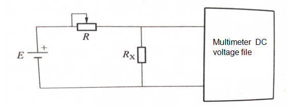
The schematic diagram of the method for measuring resistance using a multimeter DC voltage stop half voltage is shown in figure 4 / 2. In order to improve the accuracy of measurement, R adopts standard resistance box. If R is adjusted so that the indicator of the DC voltmeter equals half of E, the measured resistance Rx is equal to the reading on R.

image.png

Thursday, July 4, 2019

What's the price of XC2C256-7CPG132C IC CPLD 256MC 6.7NS 132BGA Xilinx Inc.?

Q1: What's the price of XC2C256-7CPG132C IC CPLD 256MC 6.7NS 132BGA Xilinx Inc.?
A: ALLICDATA Electronics offers more than 1,000,000  items in stock with immediate shipment,which has a competitive price.XC2C256-7CPG132C IC CPLD 256MC 6.7NS 132BGA Xilinx Inc. Real-time inventory quantity and price,please search online catalog on our website:Allicdata Electronics.

Q2: What's the delivery time of XC2C256-7CPG132C IC CPLD 256MC 6.7NS 132BGA Xilinx Inc.?
A: ALLICDATA has more than 1M + inventory, so that we can  delivere it worldwide by Fedex, DHL, UPS within 2-3 days.

Q3: How do I receive XC2C256-7CPG132C IC CPLD 256MC 6.7NS 132BGA Xilinx Inc.?
A: ALLICDATA can provide Fedex, UPS, DHL and TNT, door-to-door services, for some samples we can deliver via EMS.

Q4: How to get better price of XC2C256-7CPG132C IC CPLD 256MC 6.7NS 132BGA Xilinx Inc.?
A:For a large number, you can email us for a better price.

Q5: How to order XC2C256-7CPG132C IC CPLD 256MC 6.7NS 132BGA Xilinx Inc.?
A: You can purchase orders directly online at our website:
Open our home page >Quick search   XC2C256-7CPG132C > on Produce page click Buy > Finish all the step shows
Or send your PO to our email sales@allicata.com
Or chat with our online service.
The ordering steps are as follows:
Check price → purchase order → payment →shipment delivery out → receiving materials
For a large number, you can get a better price.

Q6:How to pay for XC2C256-7CPG132C IC CPLD 256MC 6.7NS 132BGA Xilinx Inc.?
A: ALLICDATA accepts payment by bank wire transfer (bank TT), Paypal, credit card, Western Union, letter of credit, etc. You can choose whatever way you like. We make sure that these methods are safe.

Q7: What's the MOQ of XC2C256-7CPG132C?
A: ALLICDATA MOQ  order from 1 unit.

Q8: What's quality guarantee of XC2C256-7CPG132C?
A: All ALLICDATA products are licensed by the manufacturer and are 100% NEW & ORIGINAL. If there are any problems, we accept the return within 60 days.

Q9: Where can find the pictures of XC2C256-7CPG132C IC CPLD 256MC 6.7NS 132BGA Xilinx Inc.?
A: We have provided original images of STOCK Parts. You can search for photos on our website via the search box.

Q10: How to find data sheet (PDF) of XC2C256-7CPG132C IC CPLD 256MC 6.7NS 132BGA Xilinx Inc.?
A: We have huge datasheet base.Almost all produce data sheet can be found quickly on our website. Or click this link :
If you need any help, please contact us.

Q11: Where can I find the shipping of XC2C256-7CPG132C IC CPLD 256MC 6.7NS 132BGA Xilinx Inc.?
A: You can track Fedex, DHL, UPS, TNT office websites in all our transportation. We will send a tracking link after shipping.

If this model does not meet your requirements, you can go to our website Allicdata to search for products that match. There are many kinds of products that can be selected.

XC2C256-7CPG132C Allicdata Electronics

What issues need to be considered when designing LED driver circuits?

LED has many advantages such as environmental protection, long life, high photoelectric efficiency, etc. In recent years, the application in...