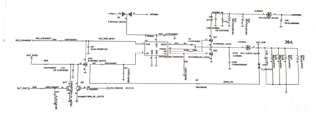
MSI produces a large number of municipal motherboards that use UP6103 chips to control motherboard memory to power electricity and bridges. Because of the high usage rate, the chip is damaged more. The UP6103 chip works as shown in figure 1.
UP6103 works as follows.
1. 12V voltage through diode D4, current limiting resistance 2.2Ω, to UP6103 5-pin power supply, UP6103 through the internal circuit to supply 1-pin power.
2. 5VDIMIN supplies the D pole of the MOS tube Q31.
3. After the tap switch is triggered, the bridge sends out a SLP_S5 high-level signal that is sent to the B pole of the transistor Q17 via the 10kΩresistor R53, making the Q17 on and the C pole pulled to a low level. The G of MOS Q18 is extremely low and Q18 is cut off. After the resistance R29 pull up the 0.9V SIO_DDR_MREF signal to the UP6103-7 feet, turn on the chip to work.
4. UP6103 controls Q31 from a 2-pin output signal, 5VDIMM_IN charges inductors and capacitors through Q31, and outputs VCC_DDR voltage to power memory.
5. After the Q31 leads, the inductor and capacitor charge slowly, and the VCC_DDR voltage will rise slowly. The VCC_DDR is sent to the 6-pin of the UP6103 chip via resistance R2, and then sampled from the resistor R4 and R37, and is compared internally with the 7-pin 0.9V voltage.
6. When the 6-pin voltage of the UP6103 is higher than 0.9V, the UP6103 controls the 2-pin output signal to turn off Q31 and turn Q35 on from the 4-pin output signal.
7. Q35 leads to the formation of a closed loop, inductance, capacitor discharge output VCC_DDR voltage for memory power supply. The VCC_DDR voltage decreases slowly during discharge and returns to the 6-pin of the UP6103 chip after sampling the anode.
8. When the 6-pin voltage of the UP6103 is less than 0.9V, the chip closes the lower Q37 and reopens the upper Q31 to charge.
9. Q31. Under UP6103 control Q37 cycle operation, after capacitor filter output smooth VCC_DDR voltage to power the memory.

Fig.1 The UP6103 chip works.

No comments:
Post a Comment